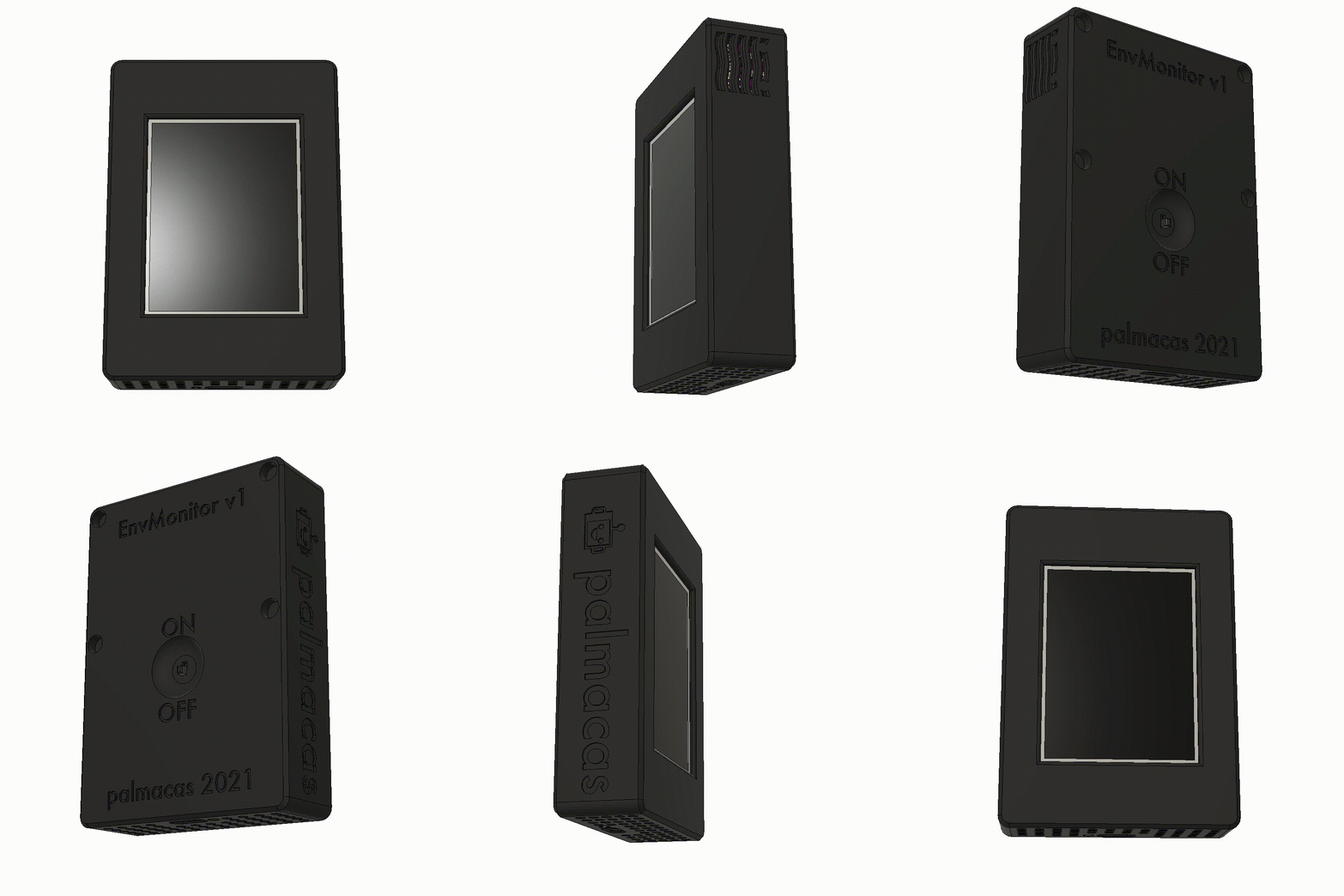
A few weeks ago, I published the Environmental Monitor project. In that post, I summarized the construction process, focusing primarily on the electronics, programming of the ESP8266, and configuration of the Nextion display. However, I left out the design and construction of the project case. This post will address those topics.

The design of the case starts around the Nextion display, being the largest element of the entire project. I initially imported a model of the display that I found on GrabCAD, and from this I created the frame and the holes for the screws that fix the display to the frame. The size of the bezels is arbitrary at the moment. From the dimensions of the created frame, a new body is generated, which is the other part of the case where the rest of the monitor components will go. The body is a solid, so the shell tool is used to remove one face and leave a hollow body with 2mm thick walls. Then it is possible to place the components inside the box, initially the TC4056A charging module is placed in the central lower part of the box and the parameters are adjusted so that it remains centered no matter if the dimensions of the box are modified, so the charging port will always remain centered.
Then the MT3608 converter can be placed to the left of the charger, and the ESP8266 Breakout Board with the ESP-01 to the right. These elements are constrained to remain aligned with the TC4056A charger. The BME280 sensor is placed on the upper right, while extrusions are added to fix the PCB to the case. Some holes are also made in the wall of the box to allow air to enter the sensor. The LiPo battery is located on the top of the box, no supports are added because it will eventually be fixed with double-sided tape. With the location of these parts, the dimensions of the frame can be better adjusted and as the design is parameterized, the measures of the monitor body are automatically updated.
The missing component is the switch to turn on and off the monitor. When looking for places to locate it, it seemed to me that it would not look good if it protruded over the volume of the case. Taking advantage of a free space between the modules and the battery, the micro-switch is located so that it can be operated from the back of the monitor. In the end, four holes are added to place the neodymium magnets, some curves to improve the appearance of the box, and a group of holes on the bottom to allow air flow and because it looked good to me. I also designed a kind of diffuser to install it on the LiPo charger LEDs to indicate the charge status.
The parts were printed in PLA, with a 0.4mm extruder, 0.2mm layers, and 30% infill. Once the parts were printed, it was only necessary to remove the supports and do some cleaning with a cutter and sandpaper. Although the white model looked good, I was afraid that eventually it would turn yellow, which is typical of PLA, so I decided to apply some primer layers, sanding between the primer layers until most of the print lines disappeared. To finish the pieces, I chose a charcoal-colored spray paint, which is a very dark matte gray. This paint is also applied in several layers and sanded between layers to achieve a better finish.
After letting everything dry completely, I started assembling all the parts, initially soldering the components and placing them inside the casing using pressure in some cases and double-sided tape in others. The frame and the body of the case are fixed using pressure.


The STL files for printing and the STEP files for use in any CAD software are available on GitHub.
GitHub: ESPEnvironmentalMonitor
If you have any questions, feel free to ask.


