
I wanted to explore more projects with the ESP8266, so I tried to create an environmental monitor that would allow me to read data from my home environment and access it from my phone or computer. The plan was to use an ESP8266 and a BME280 environmental sensor and display the data on a web page. However, while I was searching for other materials, I stumbled upon a Nextion screen that I had purchased during an Indiegogo campaign several years ago and thought I could use it as a local display point for the ESP8266.
I divided the project into stages and integrated all the parts later. I began with the electronic diagram, then read the BME280, followed by displaying the data on a web page and setting up and communicating with the Nextion screen, and finally, assembled all the components in a 3D printed case.
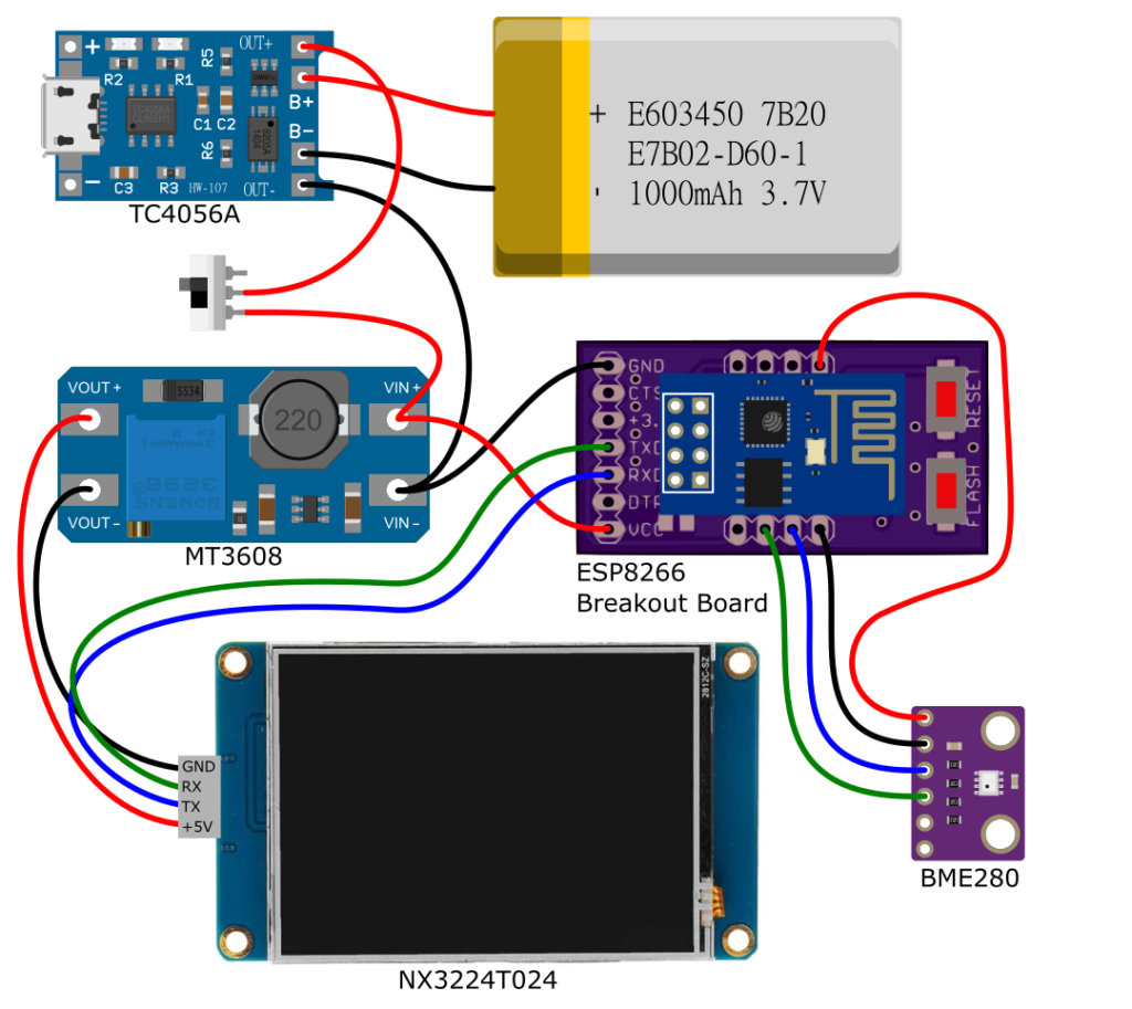
The diagram shows all the components of the monitor, with the sensor and screen connected to the ESP8266, and the power source being a 3.7V LiPo battery. The circuit also includes a USB battery charger and a step-up converter to provide the 5V required by the screen.
The BME280 sensor can measure humidity, temperature, and barometric pressure, and while it can work with SPI communication, I used I2C because the ESP-01 had limited available pins. Using the Adafruit library for the BME280 made it easy to set up communication with the sensor. However, I faced some difficulties communicating with the sensor because the ESP-01 did not have hardware I2C communication pins. So, I had to define different pins for communication and implement software I2C.To start communication with the sensor, I had to use the Wire.begin() function and specify which pins would be used for communication. When connecting to the sensor using the bme.begin() function, I had to indicate the address and interface for communication.
Adafruit_BME280 bme;
#define SDA_PIN 0
#define SCL_PIN 2
void setup() {
Wire.begin(SDA_PIN, SCL_PIN);
if (!bme.begin(0x76, &Wire)) {
Serial.println("Could not find a valid BME280 sensor, check wiring, address, sensor ID!");
while (1) delay(10);
}
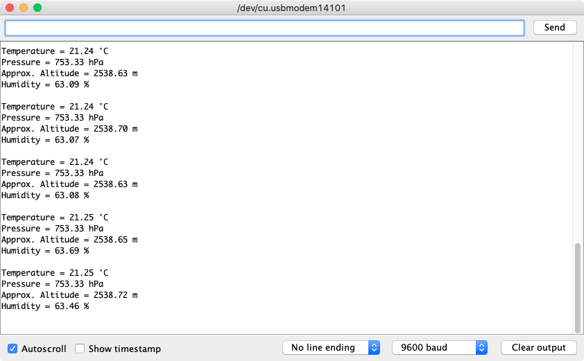
}Once communication was established with the sensor, the temperature was read in Celsius, the pressure was read in Pascals, and the barometric pressure was read in hPa or bar by dividing it by 100. To calculate the height, I only had to indicate the value of sea-level pressure, and the library would calculate the approximate height, with the average value of sea-level pressure being 1013.25 hPa. Finally, humidity was read as a percentage without any further conversions.
The next step in the project was to publish the values on a web page. While reviewing how to publish the data and make it update periodically, I considered reading other data from a weather service to present some weather information for my city. For this part, the ESP8266WiFi, ESP8266HTTPClient, ESP8266WebServer, and Arduino_JSON libraries were used.
Initially, the microcontroller connected to the WiFi network and then activated the web server, which was designed to display both weather and environmental data. Two groups of events were added to update the data periodically.
AsyncWebServer server(80);
AsyncEventSource events("/events");
AsyncEventSource local_events("/local_events");
void setup() {
  WiFi.begin(ssid, password);
  while (WiFi.status() != WL_CONNECTED) {
    delay(1000);
  }
  server.on("/", HTTP_GET, [](AsyncWebServerRequest * request) {
    request->send_P(200, "text/html", index_html, processor);
  });
  server.addHandler(&events);
  server.addHandler(&local_events);
  server.begin();
}
The weather service used was OpenWeatherMap, which offers a free API (with some restrictions). To obtain weather data, only an HTTP request to the API address was necessary, with the city, country code, and API key specified. The response could then be parsed to extract the required information for presentation.
{
"coord": {
"lon": -74.0817,
"lat": 4.6097
},
"weather": [
{
"id": 802,
"main": "Clouds",
"description": "nubes dispersas",
"icon": "03d"
}
],
"base": "stations",
"main": {
"temp": 12.73,
"feels_like": 12.36,
"temp_min": 12.73,
"temp_max": 12.73,
"pressure": 1030,
"humidity": 88
},
"visibility": 10000,
"wind": {
"speed": 3.09,
"deg": 40
},
"clouds": {
"all": 40
},
"dt": 1631452512,
"sys": {
"type": 1,
"id": 8582,
"country": "CO",
"sunrise": 1631443681,
"sunset": 1631487438
},
"timezone": -18000,
"id": 3688689,
"name": "Bogota",
"cod": 200
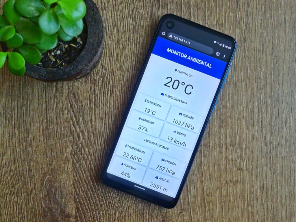
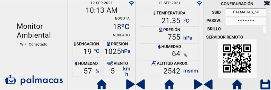
} After working with HTML, I was able to create a web page that displays the location, temperature, apparent temperature, humidity, wind speed, and weather description. All of these data were updated every 15 minutes from OpenWeatherMap. In the local readings section, the readings from the BME280 were displayed and updated every 30 seconds.
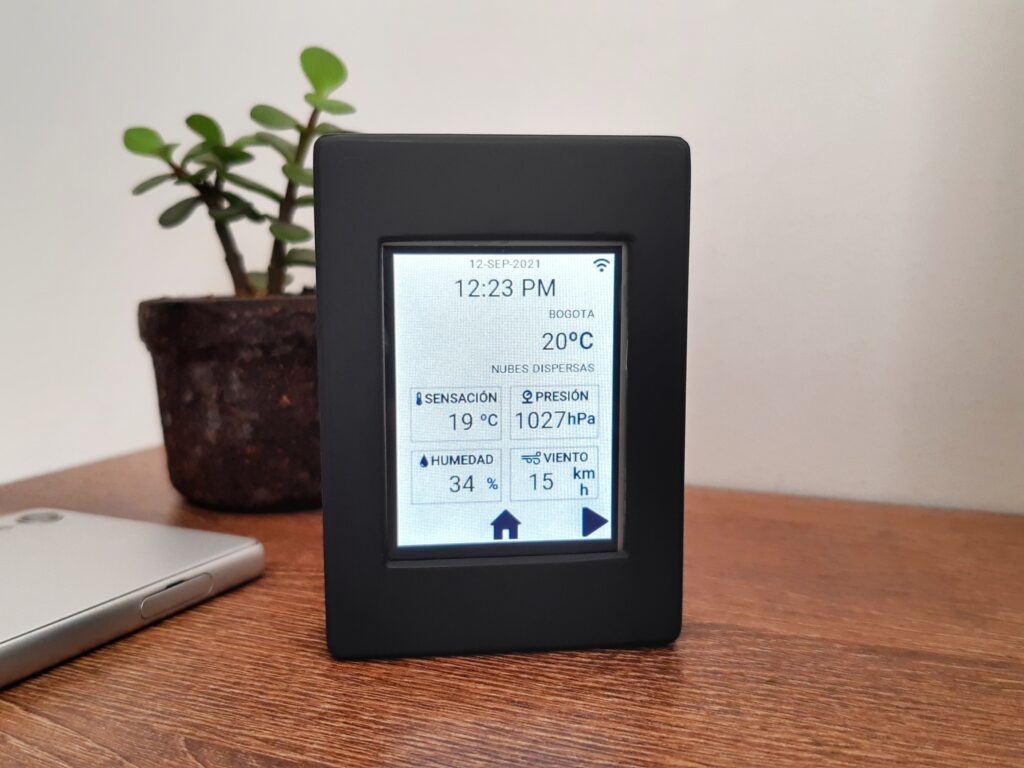
Once these advancements were made, it was time to tackle the Nextion screen. Fortunately, there was a lot of information available about its programming and communication, in various blogs and YouTube videos. The Nextion screen I used was a NX3224T024 from the basic series. This screen is 2.4 inches, with a resolution of 320 x 240 pixels and 4 MB of flash memory. It works like the industrial HMIs that are used in conjunction with PLCs. When configuring the screen, different displays were designed to display data, each with a unique name or tag. The controller, in this case the ESP8266, was responsible for updating the variables in the displays.
The monitor has four displays: one as an indication of the startup (WiFi and sensor connection), another as the main screen displaying weather status, another displaying local values, and another for configuration, which allowed entering the name and password of the WiFi network, as well as adjusting the screen brightness and IP address to access the web server.
There is an official Nextion library to control the displays with Arduino. While searching for tutorials on how to use this library, I found that the communication process is easier than expected. Essentially, you need to send the object ID, the attribute you want to change, and the assigned value, all in the form of a text string followed by three 0xFF characters. The following is a function that enables you to write commands or update values from the ESP8266 to the screen, with String cmd representing the command.
void sendCmd(String cmd)
{
  Serial.print(cmd);
  Serial.print("\xFF\xFF\xFF");
}
For instance, the object n_temp represents the temperature reading from OpenWeatherMap. To refresh this data on the screen, the following code can be used. The attribute being modified is txt and the string that will be displayed is the temperature value.
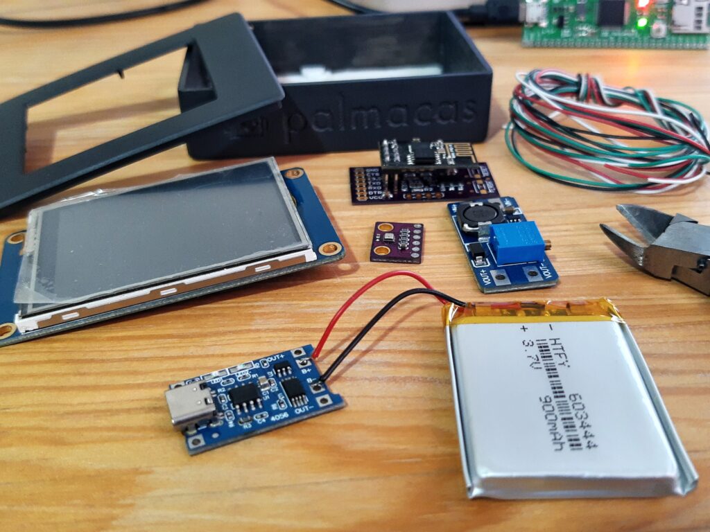
sendCmd("n_temp.txt=\""+ String(temperature) + "\"");With all the components and programming in place, I began designing a case to house all the elements of the monitor. I created the design using Fusion 360 and had it printed in PLA. After some sanding, painting, and a few more rounds of sanding and painting, I was finally able to put the monitor together. The monitor has neodymium magnets on the back, allowing it to be attached to a metal surface such as a refrigerator or similar object.
Las partes dentro del proyecto son las siguientes:
- ESP-01 (ESP8266)
- BME280 sensor
- Nextion NX3224T024 display
- ESP8266 Breakout Board
- LiPo Charger TC4056A
- Step-Up Converter MT3608
- LiPo battery 900mAh
- Two-position microswitch
During testing, when I connected the TX pin of the ESP-01 module to the RX pin of the Nextion screen, I noticed that the controller did not start. After checking forums, I found that the TX (GPIO 1) pin of the controller must be either floating or at 3.3V for the ESP8266 to start properly, and the RX of the screen was taking it to 0V. To resolve this issue, I added a 10KΩ pull-up resistor between the TX pin and 3.3V.
Finally, I established a connection to an NTP server to keep the time on the Nextion screen updated. A task that still needs to be done is to implement firmware updates for the ESP8266 using the WiFi network (OTA), so that the monitor does not need to be opened every time a change is necessary.
The complete code for the ESP8266, along with commented code, and 3D models can be found in the GitHub repository.
GitHub: ESPEnvironmentalMonitor
For more information:
Adafruit BME280 Humidity + Barometric Pressure + Temperature
API de OpenWeatherMap
Nextion
Nextion Editor
If you have any questions, feel free to ask.
Pingback: Environmental Monitor – Case – palmacas